Nand2Tetris_Part1

文章发布时间:

最后更新时间:

文章总字数:
4.3k

预计阅读时间:
21 分钟

mini版数电+计组+汇编,像搭积木一样了解计算机体系结构。

注意:计算机系统要素 从零开始构建现代计算机 ((美)NOAM NISAN,SHIMON SCHOCKEN著) (Z-Library).pdf

官网给出的课程PPT,补充了不少课本上没有的内容。

Project walkthrough

接口

1
2
3
4
5
6
7
8
9
10
11
12
13
14
15
16
17
18
19
20
21
22
23
24
25
26
27
28
29
30
31
32
33
34
35
36
37
38
39
40
41
42
43
44
45
46
47
48
49
50
51
52
53
54
55
56
57
58
59
60
61
62
63
64
 * Nand gate: Nand()
* if (a and b) out = 0, else out = 1
--------------------------------------------------------
* Not gate: Not()
* if (in) out = 0, else out = 1

* And gate: And()
* if (a and b) out = 1, else out = 0

* Or gate: Or()
* if (a or b) out = 1, else out = 0

* Exclusive-or gate: Xor()
* if ((a and Not(b)) or (Not(a) and b)) out = 1, else out = 0
--------------------------------------------------------
* Multiplexor: Mux()
* if (sel = 0) out = a, else out = b

* Demultiplexor: DMux()
* [a, b] = [in, 0] if sel = 0
* [0, in] if sel = 1
--------------------------------------------------------
* 16-bit Not gate: Not16() // And16 Or16 Mux16同理
* for i = 0, ..., 15:
* out[i] = Not(a[i])

* 8-way Or gate: Or8Way()
* out = in[0] Or in[1] Or ... Or in[7]
--------------------------------------------------------
* 4-way 16-bit multiplexor: Mux4Way16() // 8way 同理 Mux8Way16()
* out = a if sel = 00
* b if sel = 01
* c if sel = 10
* d if sel = 11


* 4-way demultiplexor: DMux4Way() // 8way 同理
* [a, b, c, d] = [in, 0, 0, 0] if sel = 00
* [0, in, 0, 0] if sel = 01
* [0, 0, in, 0] if sel = 10
* [0, 0, 0, in] if sel = 11

--------------------------------------------------------
* 16-bit adder: Add16()
* Adds two 16-bit two's complement values.
* The most significant carry bit is ignored.

* 16-bit incrementer: Inc16()
* out = in + 1

--------------------------------------------------------
* ALU (Arithmetic Logic Unit):
* Computes out = one of the following functions:
* 0, 1, -1,
* x, y, !x, !y, -x, -y,
* x + 1, y + 1, x - 1, y - 1,
* x + y, x - y, y - x,
* x & y, x | y
* on the 16-bit inputs x, y,
* according to the input bits zx, nx, zy, ny, f, no.
* In addition, computes the two output bits:
* if (out == 0) zr = 1, else zr = 0
* if (out < 0) ng = 1, else ng = 0

不难

值得一提的是 Mux 和 DMux 的设计:每位的0,1都会将输入值分为两半,两者的运算方向相反,每次都处理一半的输入,例如从16->8->4->2->1+1。

1
2
3
4
5
6
7
8
9
10
11
12
13
14
15
16
17
18
19
20
21
22
23
24
25
26
27
28
29
30
31
32
33
34
35
36
37
38
39
40
41
42
43
44
45
46
47
48
49
50
51
52
53
54
55
56
57
58
59
60
61
62
63
64
65
66
67
68
69
70
71
72
73
74
75
76
77
78
79
80
81
82
83
84
85
86
87
88
89
90
91
92
93
94
95
96
97
98
99
100
101
102
103
104
105
106
107
108
109
110
111
112
113
// This file is part of www.nand2tetris.org
// and the book "The Elements of Computing Systems"
// by Nisan and Schocken, MIT Press.
// File name: projects/1/DMux8Way.hdl

/**
* Multiplexor:
* if (sel = 0) out = a, else out = b
*/
CHIP Mux {
IN a, b, sel;
OUT out;

PARTS:
//// Replace this comment with your code.
// sel and b or ~sel and a
And(a= sel, b= b, out= ob);
Not(in= sel, out= ns);
And(a= ns, b= a, out= oa);
Or(a= oa, b= ob, out= out);
}


/**
* Multiplexor:
* if (sel = 0) out = a, else out = b
*
* Demultiplexor:
* [a, b] = [in, 0] if sel = 0
* [0, in] if sel = 1
*/
CHIP DMux {
IN in, sel;
OUT a, b;

PARTS:
// if ~sel then a = in
// else b = in
Not(in= sel, out= ns);
Mux(a= in, b= false, sel= sel, out= a);
Mux(a= in, b= false, sel= ns, out= b);
}


/**
* 4-way 16-bit multiplexor:
* out = a if sel = 00
* b if sel = 01
* c if sel = 10
* d if sel = 11
*/
CHIP Mux4Way16 {
IN a[16], b[16], c[16], d[16], sel[2];
OUT out[16];

PARTS:
//// Replace this comment with your code.
// sel[1] = 0 在a,b中选择; sel[0] = 0 >> a
Mux16(a= a, b= b, sel= sel[0], out= ab);
Mux16(a= c, b= d, sel= sel[0], out= cd);
Mux16(a= ab, b= cd, sel= sel[1], out= out);
}


/**
* 4-way demultiplexor:
* [a, b, c, d] = [in, 0, 0, 0] if sel = 00
* [0, in, 0, 0] if sel = 01
* [0, 0, in, 0] if sel = 10
* [0, 0, 0, in] if sel = 11
*/
CHIP DMux4Way {
IN in, sel[2];
OUT a, b, c, d;

PARTS:
//// Replace this comment with your code.
// DMux 实现了对a,b的分配 sel->a, ~sel->b
DMux(in= in, sel= sel[1], a= ab, b= cd);
DMux(in= ab, sel= sel[0], a= a, b= b);
DMux(in= cd, sel= sel[0], a= c, b= d);
}


/**
* 8-way demultiplexor:
* [a, b, c, d, e, f, g, h] = [in, 0, 0, 0, 0, 0, 0, 0] if sel = 000
* [0, in, 0, 0, 0, 0, 0, 0] if sel = 001
* [0, 0, in, 0, 0, 0, 0, 0] if sel = 010
* [0, 0, 0, in, 0, 0, 0, 0] if sel = 011
* [0, 0, 0, 0, in, 0, 0, 0] if sel = 100
* [0, 0, 0, 0, 0, in, 0, 0] if sel = 101
* [0, 0, 0, 0, 0, 0, in, 0] if sel = 110
* [0, 0, 0, 0, 0, 0, 0, in] if sel = 111
*/
CHIP DMux8Way {
IN in, sel[3];
OUT a, b, c, d, e, f, g, h;

PARTS:
//// Replace this comment with your code.
// 对MUX的逆向
DMux(in= in, sel= sel[2], a= abcd, b= efgh);
DMux(in= abcd, sel= sel[1], a= ab, b= cd);
DMux(in= efgh, sel= sel[1], a= ef, b= gh);
DMux(in= ab, sel= sel[0], a= a, b= b);
DMux(in= cd, sel= sel[0], a= c, b= d);
DMux(in= ef, sel= sel[0], a= e, b= f);
DMux(in= gh, sel= sel[0], a= g, b= h);
}

学东西就留下具体实践解决生活问题这才是技术之根本 。

ALU 完成

1
2
3
4
5
6
7
8
9
10
11
12
13
14
15
16
17
18
19
20
21
22
23
24
25
26
27
28
29
30
31
32
33
34
35
36
37
38
39
40
41
42
43
44
45
46
47
48
49
50
51
52
53
54
55
56
57
58
59
60
61
62
63
64
65
66
67
68
69
70
71
72
73
74
75
76
77
78
79
80
81
82
83
84
85
86
87
88
89
90
91
92
93
94
95
// This file is part of www.nand2tetris.org
// and the book "The Elements of Computing Systems"
// by Nisan and Schocken, MIT Press.
// File name: projects/2/ALU.hdl
/**
* ALU (Arithmetic Logic Unit):
* Computes out = one of the following functions:
* 0, 1, -1,
* x, y, !x, !y, -x, -y,
* x + 1, y + 1, x - 1, y - 1,
* x + y, x - y, y - x,
* x & y, x | y
* on the 16-bit inputs x, y,
* according to the input bits zx, nx, zy, ny, f, no.
* In addition, computes the two output bits:
* if (out == 0) zr = 1, else zr = 0
* if (out < 0) ng = 1, else ng = 0
*/
// Implementation: Manipulates the x and y inputs
// and operates on the resulting values, as follows:
// if (zx == 1) sets x = 0 // 16-bit constant
// if (nx == 1) sets x = !x // bitwise not
// if (zy == 1) sets y = 0 // 16-bit constant
// if (ny == 1) sets y = !y // bitwise not
// if (f == 1) sets out = x + y // integer 2's complement addition
// if (f == 0) sets out = x & y // bitwise and
// if (no == 1) sets out = !out // bitwise not

CHIP ALU {
IN
x[16], y[16], // 16-bit inputs
zx, // zero the x input?
nx, // negate the x input?
zy, // zero the y input?
ny, // negate the y input?
f, // compute (out = x + y) or (out = x & y)?
no; // negate the out output?
OUT
out[16], // 16-bit output
zr, // if (out == 0) equals 1, else 0 零标记
ng; // if (out < 0) equals 1, else 0 负数标记

PARTS:
//// Replace this comment with your code.

// x 经过标志位后可能为 x, 0, !x, !0
Mux16(a= x, b= false, sel= zx, out= XorZero);
Not16(in= XorZero, out= negateX);
Mux16(a= XorZero, b= negateX, sel= nx, out= newX);
Mux16(a= y, b= false, sel= zy, out= YorZero);
Not16(in= YorZero, out= negateY);
Mux16(a= YorZero, b= negateY, sel= ny, out= newY);

// 完成 加法,与运算
Add16(a = newX, b = newY, out = sum);
And16(a= newX, b= newY, out= logic);

Mux16(a= logic, b= sum, sel= f, out= dirOut);
Not16(in= dirOut, out= NdirOut);

// 输出
Mux16(a= dirOut, b= NdirOut, sel= no, out= out1);
And16(a= out1, b= true, out[0..7]= olow, out[8..15]= ohigh);
Or8Way(in= olow, out= lhas1);
Or8Way(in= ohigh, out= hhas1);
Or(a= lhas1, b= hhas1, out= has1);
Not(in= has1, out= zr);

And16(a= out1, b= true, out[15]= isneg);
And(a= isneg, b= isneg, out= ng);

And16(a= out1, b= true, out= out);


/*
// 处理 zx nx zy ny -> XorZero YorZero negateX negateY
Mux16(a= x, b= false, sel= zx, out= XorZero);
Not16(in= XorZero, out= negateX);
Mux16(a= y, b= false, sel= zy, out= YorZero);
Not16(in= YorZero, out= negateY);

// 选择 x 或 zx 作为用于下一步运算
Mux(a= x, b= XorZero, sel= zx, out= );


// 处理 f 运算 -> xpy (x+y) xay (x&y)
Add16(a = x, b = y, out = xpy);
And16(a= x, b= y, out= xay);

// 处理 out 结果 和 zr ng 标签
*/


}

本ALU没有涉及时序逻辑中的shift功能。

2024/10/16

Project 3 时序逻辑

It’s a poor sort of memory that only works backward.

记忆如此悲怜,只能回溯过去。

—- Lewis Carroll (1832 ~ 1898 ) , 英国作家

接口

1
2
3
4
5
6
7
8
9
10
11
* 1-bit register: Bit()
* If load is asserted, the register's value is set to in;
* Otherwise, the register maintains its current value:
* if (load(t)) out(t+1) = in(t), else out(t+1) = out(t)

* 16-bit register: Register()
* If load is asserted, the register's value is set to in;
* Otherwise, the register maintains its current value:
* if (load(t)) out(t+1) = int(t), else out(t+1) = out(t)

* 8 Way 16-bits Memory: RAM8()

还得绕一下,把输出接到输入,所有第一步其实在第二步的后面。

1
2
3
4
5
6
7
8
9
10
11
12
13
14
15
16
17
18
19
/**
* 1-bit register:
* If load is asserted, the register's value is set to in;
* Otherwise, the register maintains its current value:
* if (load(t)) out(t+1) = in(t), else out(t+1) = out(t)
*/
CHIP Bit {
IN in, load;
OUT out;

PARTS:
// 注意有一个时钟t信号

// 2. 选择写入新数据或旧数据
Mux(a= old, b= in, sel= load, out= new);

// 1. 输出接回到mux作待选择信号
DFF(in= new, out= old, out = out);
}

内存的设计也很巧妙,将load信号进行分配。

1
2
3
4
5
6
7
8
9
10
11
12
13
14
15
// 此处按照地址分配正确的load信号,接受到load的那一条路才会进行数据操作
DMux8Way(in= load, sel= address, a= l1, b= l2, c= l3, d= l4, e= l5,
f= l6, g= l7, h= l8);

Register(in= in, load= l1, out= r1);
Register(in= in, load= l2, out= r2);
Register(in= in, load= l3, out= r3);
Register(in= in, load= l4, out= r4);
Register(in= in, load= l5, out= r5);
Register(in= in, load= l6, out= r6);
Register(in= in, load= l7, out= r7);
Register(in= in, load= l8, out= r8);

Mux8Way16(a= r1, b= r2, c= r3, d= r4, e= r5, f= r6, g= r7, h= r8,
sel= address, out= out);

RAM64: 地址线高三位先选择某片内存,低三位在raw内选存储器

PC: 可以置零,加一,输入新值,频繁更改。注意标志位的处理顺序

1
2
3
4
5
6
7
8
9
10
11
12
13
14
15
CHIP PC {
IN in[16], reset, load, inc;
OUT out[16];

PARTS:
// 功能:置零,输入,保持,加一
Inc16(in= old, out= Inc);
Mux16(a= old, b= Inc, sel= inc, out= ifInc);
Mux16(a= ifInc, b= in, sel= load, out= ifIn);
Mux16(a= ifIn, b= false, sel= reset, out= fin);

// 注意:load输入仅控制是否写入in[16],不应影响reset,inc的写入
Register(in= fin, load= true, out= old, out=out);

}

2024/10/19

Project 4 汇编

我写汇编?真的假的?

Before the porject…

These files should be stored in your browser’s local storage by the web IDE.
这些文件应该通过Web IDE存储在浏览器的本地存储中。

Add.asm, Max.asm, Rect.asm, and Pong.asm should be in the Project 6 folder.
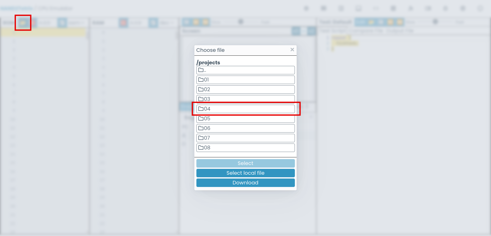
Add.asm、Max.asm、Pong.asm和Pong.asm应位于Project 6文件夹中。

They can be accessed through the “Load file” button in either the CPU emulator or the assembler, as depicted here:
它们可以通过CPU模拟器或汇编器中的“加载文件”按钮访问,如下所示:

If you don’t see the folders for projects 4 and 6 in there, please try resetting your files (Settings > Reset) and let me know if this fixes the issue.
如果你没有在那里看到项目4和6的文件夹,请尝试重置你的文件(设置 > 重置),并让我知道这是否解决了问题。

(Note that this will clear the browser’s local storage, deleting your saved files, so make sure you back everything up before doing that!)
(Note这将清除浏览器的本地存储,删除您保存的文件,所以请确保您备份一切之前这样做!)

来自:从第一原理构建现代计算机:从 Nand 到俄罗斯方块(以项目为中心的课程) - 讨论 | Coursera

从这一章开始该仔细读project文档了,项目 4:机器语言

在开始汇编之前,文档推荐先去proj6文件夹下感受一下汇编代码,给出了几个示例文件:加法,求max,经典弹球游戏之类的。将文件load进汇编器里,然后translate all将汇编转为机器码,完成后在binary code板块将其加载到cpu模拟器中运行。

注意:如果你编写的汇编代码需要使用目的地 DM=… 或 ADM=…,请改用 MD=… 或 AMD=…。

Hack 语言是区分大小写的。

另一个常见错误是在编写指令时使用小写字母或空格。例如,m=1 或 M = 1 都会导致语法错误。正确的语法是 M=1

最佳实践:

  • 使用大写字母为标签,如 LOOP,使用小写字母为变量,如 sum。
  • 缩进你的代码:将所有不是标签声明的行向右缩进几个字符。
  • 根据需要编写注释,以使你的代码清晰。
  • 查看讲座或书籍中的程序,并遵循它们的示例。
  • 像往常一样,努力编写优雅、高效且自解释的程序。

简单理解一下:Hacker计算机内部有A,D(a.k.a. address data)两个寄存器和可按地址访问的内存M[address]。将数或地址写入A寄存器的语法为@value,与M配合使用可进行访存,也可当作存储数字的寄存器使用,例如:

1
2
3
4
5
6
7
@5	// A = 5, echo A 输出 5
D=A // D = 5

@i // 不存在于预设的名称将在内存中为其划分一块存储空间,命名为 i
// 此时寄存器A内存储i所在的地址
M=6 // 此时相当于访问内存中为5的数据(Memory[5]),并存入数字 5
D=M // 将Memory[5]的值放入D寄存器,此时 echo D 输出 6

闹麻了,卡了好几天了,让我看看怎么个事:

分析一下给出的汇编代码:主要是跳转指令有些模糊,使用了标志作为语法糖辅助跳转,思想与C中的goto一致,避免调用JMP指令时还需要程序员数行号进行跳转。跳转语句结构形如D;JMP,D为放入ALU计算的值,JMP指令根据ALU计算后的返回值按需跳转。

标志的结构为 (SYMBOL)括号括助,内部一般使用全大写表示,JMP语句调用前使用@SYMBOL将标志地址导入A寄存器,跳转语句将跳转至A寄存器所指的指令位置(行号)

完成后的程序需要将其卡住在程序的底部,防止PC增长,越界执行非法代码。

部分代码

1
2
3
4
5
6
7
8
9
10
11
12
13
14
15
16
17
18
19
20
21
22
23
24
25
26
27
28
29
30
31
32
33
34
35
36
37
38
39
/*
int i = 0;
int R2 = 0;
while (i > 0) {
R2 += R0;
i--;
}
*/

(LOOP)
// if i == 0 end the loop and go out
@i
D=M
@NEXT
D;JLE
// else i > 0 then sum += R0, i -= 1
@sum
D=M // D[sum]
@R0
D=D+M // sum += R0
@sum
M=D // 将计算结果从内存的sum处写入R2处
@i
M=M-1 // i -= 1


@LOOP
0;JMP // back to loop

(NEXT)
@sum
D=M
@R2
M=D // 将sum的值存进R2

(END)
// 无条件跳转,将程序控制在程序的最底部
@END
0;JMP

IO部分更为有趣,从print到屏幕上对应hello world的像素亮起中间到底发生了什么,我很好奇。其实没有什么难的,内存中除了保存数据的部分,也有专门划分的用于保存显示器每个像素颜色的区域,调整这一小块内存的值就能改变对应像素的颜色,键盘输入也有一个专门的地址保存,CPU按需读取。

下一章将完成从CPU到computer的实现,激动人心。

Project 5 计算机体系结构

已给接口

1
2
3
4
A/DRegister(in[16], load, out[16])
ALU(x[16],y[16],zerox,negtivex,zy,ny,func,negout, out[16],if0,ifneg)
ROM32K(in:address[15], out[16])
PC(in[16],ifreset,ifload,ifInc,out[16])

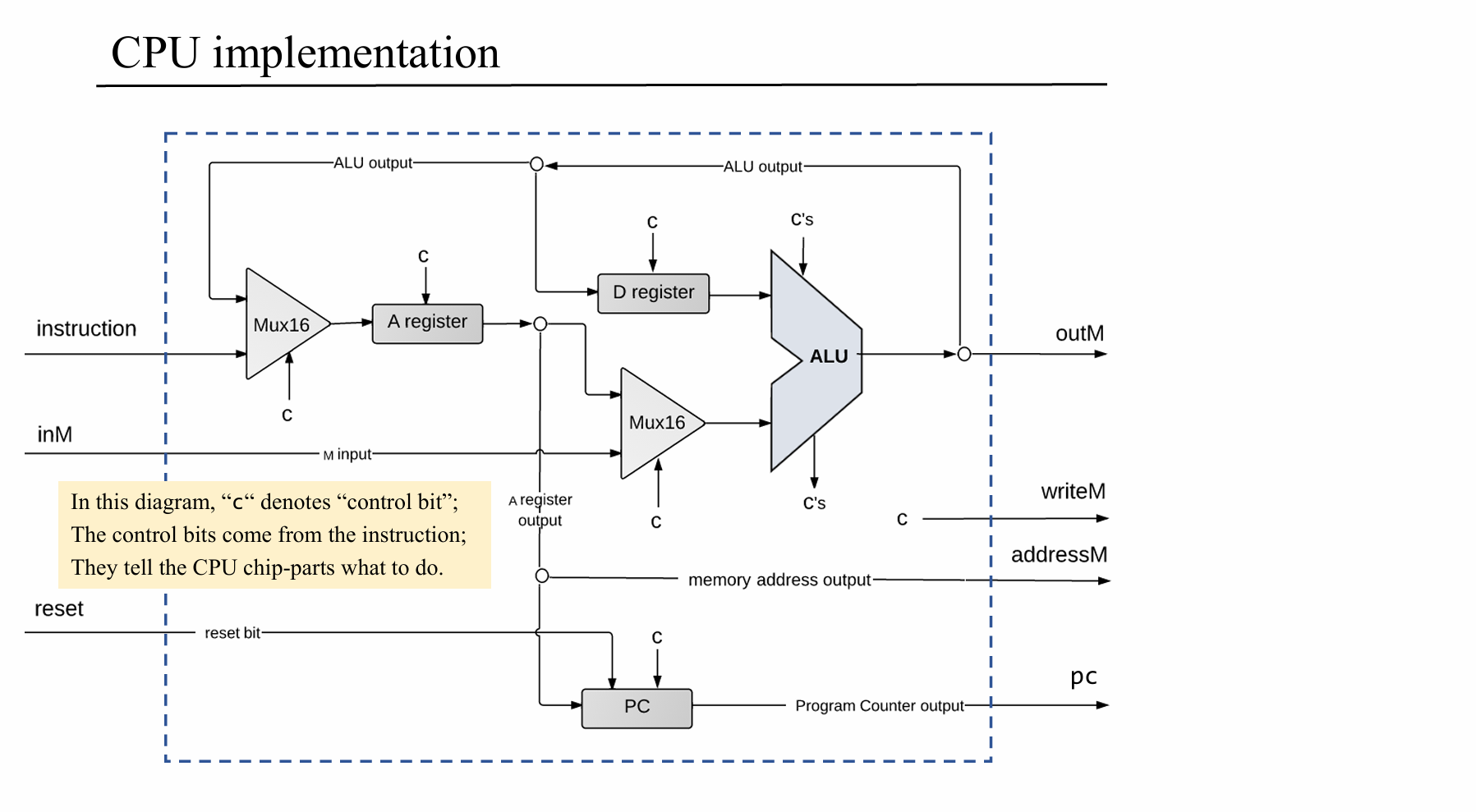
主要目标是完成CPU的设计,考虑到复杂性,已经给出大致设计:

指令或上一步输出经选择存入A寄存器,分两支处理

1 指令存入A寄存器

A指令:[0 value*15]

C指令:[111 acccccc ddd jjj]分别按指令位执行计算,存入目的地,是否跳转 。 a-位域决定ALU是把A寄存器的输入当作操作数,还是把内存单元的输入当作 操作数

可见d1决定是否写入A寄存器,d2决定D,d3决定M

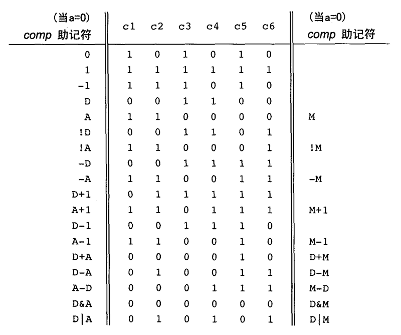
由下图可见,c是ALU的参数,d和j需要单独处理,图中未标出。

注意到指令中不同位与图中控制位的颜色有对应关系

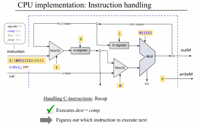
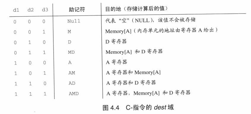
把流程理一下:指令内存传入指令instruction,Memory out端传入inM信号,通过ins[15]的值判断Areg存入指令还是上次计算的结果。c指令,接下来将ALU标志位传入ALU,d位分别传入A,Dreg和最终输出位writeM决定是否写入A,D,M中。然后是j位是跳转条件,根据ALU两个输入之差的正负判断大于小于情况,与JMP要求相符则同意PC的下一时刻的值为Areg中的目标地址。否则PC自律(自增,重置…)。最终CPU输出out写入内存中(如果d位同意的话)

1
2
// C指令必须是1开头  [ixx acccccc ddd jjj]
// index: FED CBA9876 543 210

a位域0表示将A reg作为数值计算,1表示作为内存读取

以汇编代码@5 D=A为例解析:

A指令传入,Mux选择指令写入Areg,A指令结束。

C指令从Areg与inM中选择Areg的值传入ALU,不进行计算直接输出,途径load态Dreg将数值写入,跳转码为000,不执行。Areg,Memory为非load态,不写入数据。C指令结束。

还需处理JMP指令,通过ALU的输出进行判断大于小于条件是否成立,作为PC的load条件,in为A reg的值,当load成立,则PC转入A指向的值;否则PC正常自增。

注意:ALU及其他c位域必须在c指令时才生效(And检验instruction[15] & instruction[c])

至此CPU的运行逻辑就很清晰了,务必自行设计汇编案例通过人脑模拟CPU。

来自fkgkdfgy的HDL代码,太优雅了

1
2
3
4
5
6
7
8
9
10
11
12
13
14
15
16
17
18
19
20
21
22
23
24
25
26
27
28
29
30
31
32
33
34
35
36
37
38
PARTS:
// Put your code here:
// A Register pipeline
Mux16(a=instruction,b=outALU,sel=instruction[15],out=inA);
And(a=instruction[15],b=instruction[5],out=insCloadA);
Not(in=instruction[15],out=insAloadA);
Or(a=insAloadA,b=insCloadA,out=loadA);
Register(in=inA,load=loadA,out=outA,out[0..14]=addressM);
Mux16(a=outA,b=inM,sel=instruction[12],out=outAorM);

// D Register pipeline
And(a=instruction[15],b=instruction[4],out=loadD);
Register(in=outALU,load=loadD,out=outD);

// PC pipeline
Or(a=outzr,b=outng,out=interresult);
Not(in=interresult,out=pos);
And(a=instruction[2],b=outng,out=statNg);
And(a=instruction[1],b=outzr,out=statZero);
And(a=instruction[0],b=pos,out=statPos);
Or(a=statNg,b=statPos,out=statInter1);
Or(a=statInter1,b=statZero,out=statInter2);
And(a=statInter2,b=instruction[15],out=loadPC);

Or(a=loadPC,b=reset,out=notinc);
Not(in=notinc,out=incPC);
PC(in=outA,
inc=incPC,load=loadPC,reset=reset,
out[0..14]=pc);

// ALU pipeline
ALU(x=outD,y=outAorM,
zx=instruction[11],nx=instruction[10],
zy=instruction[9],ny=instruction[8],
f=instruction[7],no=instruction[6],
out=outALU,zr=outzr,ng=outng,
out=outM);
And(a=instruction[15],b=instruction[3],out=writeM);

Computer

汇编代码烧录到ROM指令内存后由ROM和CPU交互,接受PC的地址,将对应地址的指令传入CPU。计算过程与数据内存进行读写。
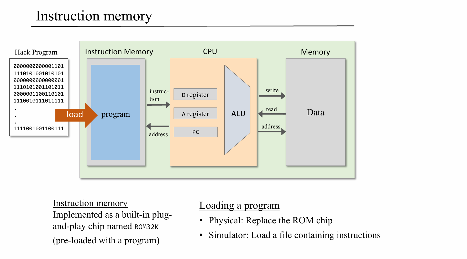
1
2
3
4
5
6
7
8
9
10
11
12
13
14
CHIP Computer {

IN reset;

PARTS:
//// Replace this comment with your code.
CPU(inM= fromMtoCPU, instruction= newInstruction, reset= reset, outM= CPUout,
writeM= writeEnable, addressM= CPUwriteInMemory, pc= askForNewInstruction);

ROM32K(address= askForNewInstruction, out= newInstruction);

Memory(in= CPUout, load= writeEnable, address= CPUwriteInMemory, out= fromMtoCPU);

}

代码稍微有一点点绕,把输出变量名写清晰就好多了。

接下来的软件部分后续可能会抽时间慢慢做,先啃OS去了。

参考

Nand2Tetris 通关感想 - 知乎

nand2tetris_hack计算机 - 柠檬水请加冰 - 博客园

GitHub - fkgkdfgy/from_nand_2_tetris